How to Build Remote Cpntrol LED Ribbon
 DIY Remote Control LED Ribbon
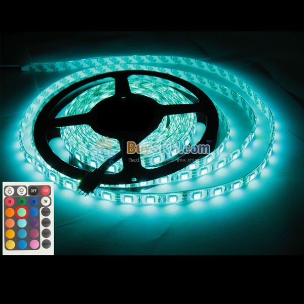
Building an LED ribbon can provide additional lighting down one wall in any room of the house. An LED ribbon is a flexible circuit board that contains SMD LEDs. These ribbon lights provide some versatile lighting options. In most cases, the ribbons use 12 volts and most of them are about 5 meters long. Their power requirements can range from just a few watts per meter up to 15 watts or more per meter. Normally, there are series of 3 LEDs that are connected using a current limiting resistor and each group of LEDs are connected in parallel. These are all connected to the supply voltage rails that run along the ribbon. The ribbon can be cut to certain lengths to meet the specific need making them a great option for a DIY remote control project. To complete this project the DIY hobbyist will need to have some previous experience in working with electrical parts and components as well as a basic working knowledge of how electricity works.
Mounting the LEDs
The first thing that needs to be done to set up the remote controlled lighting is to mount the LEDs. The ribbon comes with an adhesive tape so that it can be glued onto any surface that is flat. Some prefer to attach it to an aluminum profile. This is a good idea but you just have to be careful to make certain that the electrical contacts are isolated safely away from the aluminum. The aluminum contains a protective layer but you want to be sure that you do not risk a short circuit. Once the ribbon is attached to the profile it can be mounted on the wall using curtain rod holders.
Testing the Software and Circuits
The LED is usually driven using a standard 12V DC power supply which provides adequate power. It is also possible to use a simple switch to supply power but it is more fun to design it so that it will dim from an infrared remote controller. Dimming can be accomplished by using a PWM (pulse-width modulation) from any Atmel ATtiny 25 microcontroller. The PWM sends a signal to the gate of the MOSFET which actually controls the current that goes through the LED ribbon. It controls it by switching to the ground side of the ribbon. To ensure that there is no flickering, the PWM has to be set high enough. To ensure that the progression avoids flickering you can use these settings:
· 8MHz internal oscillator
· 64 PWM steps
· Phase correct PWM on the timer set to 0
This results in about 60 kHz of frequency for the PWM. This keeps flickering at a minimum but can still have a little rough progression to the lowest dim setting. Also the receiver for the infrared remote controls is attached to the PB3 of the ATtiny. You may choose to use an IR remote control library (IRMP) which will support a lot of different remote controls successfully. It is also possible to use the remote from another LED ribbon. Some also choose to use the on/off codes and the dim codes from the controller. It’s up to the personal preference of the builder as to what type of remote controller is used. It’s also a good idea to build a prototype of the circuit on a breadboard just to test it and then move it to the 3-island stripped Vero board.
Parts for Putting the RC Together
Here is the list of components that are needed to build the remote controller:
· ATtiny25 microcontroller
· Power MOSFET (IRFZ44)
· 78L05 voltage regulator
· 10kohm resistor
· 150ohm resistor
· Infrared remote receiver
· 100uF electrolytic capacitor
· A section of perfboard
It is possible to create a PCB layout for your controller, but you do not have to. You’ll have to use source code to program the controller and you can use a precompiled binary. If you use some other type of remote control, you will have to search to find the codes used for the remote control and change the lines in the file that correspond. Compiling code should fit in the smallest of the Attiny devices:
· Program 1762 bytes (86% full) – (.text + .data + .boot loader)
· Data 46 bytes (35.0% full) – (.data + .bss + .noinit)
